
I recently came across a very interesting GDC talk by Matt Nava on some of the tricks used in the art of ABZÛ, and I was really fascinated by it. Not because it featured anything super-complex and amazingly innovative, but because it featured some great ways technical art was used to solve problems. And those problems were not just for optimization purposes, but for game design as well. Being interested in every aspect of game development, I loved how these different aspect went hand in hand.
More specifically, the thing that got me excited the most was the so called “portal cards” (mentioned at 18 minutes in). That trick got me so intrigued mostly due to its simplicity. I thought of a rather easy way of replicating it (at least to some level) and it is a great tool for aesthetic enhancement as well as to guide the player, as mentioned by Nava.
Almost immediately after I finished the video, I opened Unity and just made a version of that effect via shaders, and the result is as follows:
Since this post is not basically a tutorial but more like a demonstration, I won’t go into too much detail. I’m thinking however about making a post of shader technique tips, like getting the distance from the camera (as shown below). So stay tuned for that!
Let’s move to the code:
Shader "Unlit/PortalCard"
{
	Properties
	{
		_MainTex ("Texture", 2D) = "white" {}
		_BaseColor("Base color", color) = (1,1,1,1)
		_MaxCamDist("Max Camera distance", float) = 100
		_MinAlphaValue("Min alpha value", Range(0.0, 1.0)) = 0.0
		_MaxAlphaValue("Max alpha value", Range(0.0, 1.0)) = 1.0
		_FallOffU("Falloff U", float) = 0.0
		_FallOffV("Falloff V", float) = 0.0
	}
	SubShader
	{
		Tags {"Queue"="Transparent" "RenderType"="Transparent" }
        LOD 100

        ZWrite Off
        Blend SrcAlpha OneMinusSrcAlpha

		Pass
		{
			CGPROGRAM
			#pragma vertex vert
			#pragma fragment frag

			#include "UnityCG.cginc"

			struct appdata
			{
				float4 vertex : POSITION;
				float2 uv : TEXCOORD0;
			};

			struct v2f
			{
				float2 uv : TEXCOORD0;
				float4 vertex : SV_POSITION;
				float4 worldPos : TEXCOORD1;
			};

			sampler2D _MainTex;
			float4 _MainTex_ST;
			float4 _BaseColor;
			float _MaxCamDist;
			float _MinAlphaValue;
			float _MaxAlphaValue;
			float _FallOffU;
			float _FallOffV;

			v2f vert (appdata v)
			{
				v2f o;
				o.vertex = UnityObjectToClipPos(v.vertex);
				o.uv = TRANSFORM_TEX(v.uv, _MainTex);
				UNITY_TRANSFER_FOG(o,o.vertex);
				o.worldPos = mul(unity_ObjectToWorld, v.vertex);
				return o;
			}

			fixed4 frag (v2f i) : SV_Target
			{
				const float PI = 3.14159;
				fixed4 col = tex2D(_MainTex, i.uv) * _BaseColor;
				float camDist = distance(i.worldPos, _WorldSpaceCameraPos);
				col.a =  lerp(_MinAlphaValue, _MaxAlphaValue, saturate(camDist/_MaxCamDist));
				float falloffU = pow((sin(i.uv.x * PI) + 1) / 2, _FallOffU);
				float falloffV = pow((sin(i.uv.y * PI) + 1) / 2, _FallOffV);
				col.a *= falloffU * falloffV;
				return col;
			}
			ENDCG
		}
	}
}
It’s nothing more than what’s mentioned in the talk. It’s just a transparent material where the opacity is determined by the distance of the object from the camera, based on a max distance value. The extra thing I made sure to notice was to remove the code to apply fog to the material. Since those “portal cards” were used to show passages hidden by fog, they would be quite useless if the were also occluded by the fog. Other than that, I added the tags to declare the material as transparent, and I move on to the vertex shader. There I got the world position of the object (line 57), which was done by multiplying the vertex position of the object by a special Unity-declared matrix. In order to store it in the v2f struct, I declared it in line 39.
Since this shader is all about color (and the alpha channel to be more specific), it’s only logical that the whole thing works inside the fragment shader. After declaring PI (because everybody loves π) I get the default color of the plane based on the main texture and tint. So yeah, we can also add a texture in the plane, if that’s what we want. After that, I get the distance of the object from the camera using the, oh so convenient, “distance” function, the world position of our object (that we got in the vertex shader) and the world space position of the camera which is generously given to us by Unity’s built-in value “_WorldSpaceCameraPos”. By the way, there are plenty of cool built-in values which you can check here:
I have declared as parameters a minimum and a maximum value for the alpha of our object, in case I don’t want it to fade completely or to be completely opaque when far away. For the default behavior though, the minimum alpha value should be 0 and the maximum should be 1. So, in line 66 I lerp between those 2 values using the result of the division of the distance by the declared maximum camera distance. Just to be safe, I also clamp the result from 0 to 1 using “saturate”. The result of the lerp is assigned as the alpha value of our final color.
It’s not seen in the video, but I also kinda implemented the “falloffU/V” thing shown in the talk. As the _FallOffU value increases, the plane will fade from the top and bottom to the center, while as the _FallOffV value increases, it will fade from left and right to the center. This allows to have some freedom when it comes to the shape of our “card”. Therefore, I use lines 67 and 68 to calculate a horizontal and a vertical column respectively, which are both fading outwards. The “pow” function is to adjust the intensity of the effect based on _FallOffU/V. The reason I used the sin function like that can get clearer if you see what the function y = sin(x * PI) looks when x is in [0,1]:
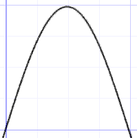
The y gets to it’s higher value in the middle of the domain smoothly. Which is basically what we want for both x and y axes using the falloff: to be zero at the edges and 1 at the center. The falloff values are multiplied with our previous alpha value, and the final color is returned.
I’m sure the great developers at “Giant Squid Studios” created something more complex than what I hacked together in 10′, but I believe that’s a good way to start approaching such an effect. After that, one can add more control over more stuff and see whatever needs to be added based on the needs of his/her project.
Bonus
Here’s the same effect in a UE4 material:
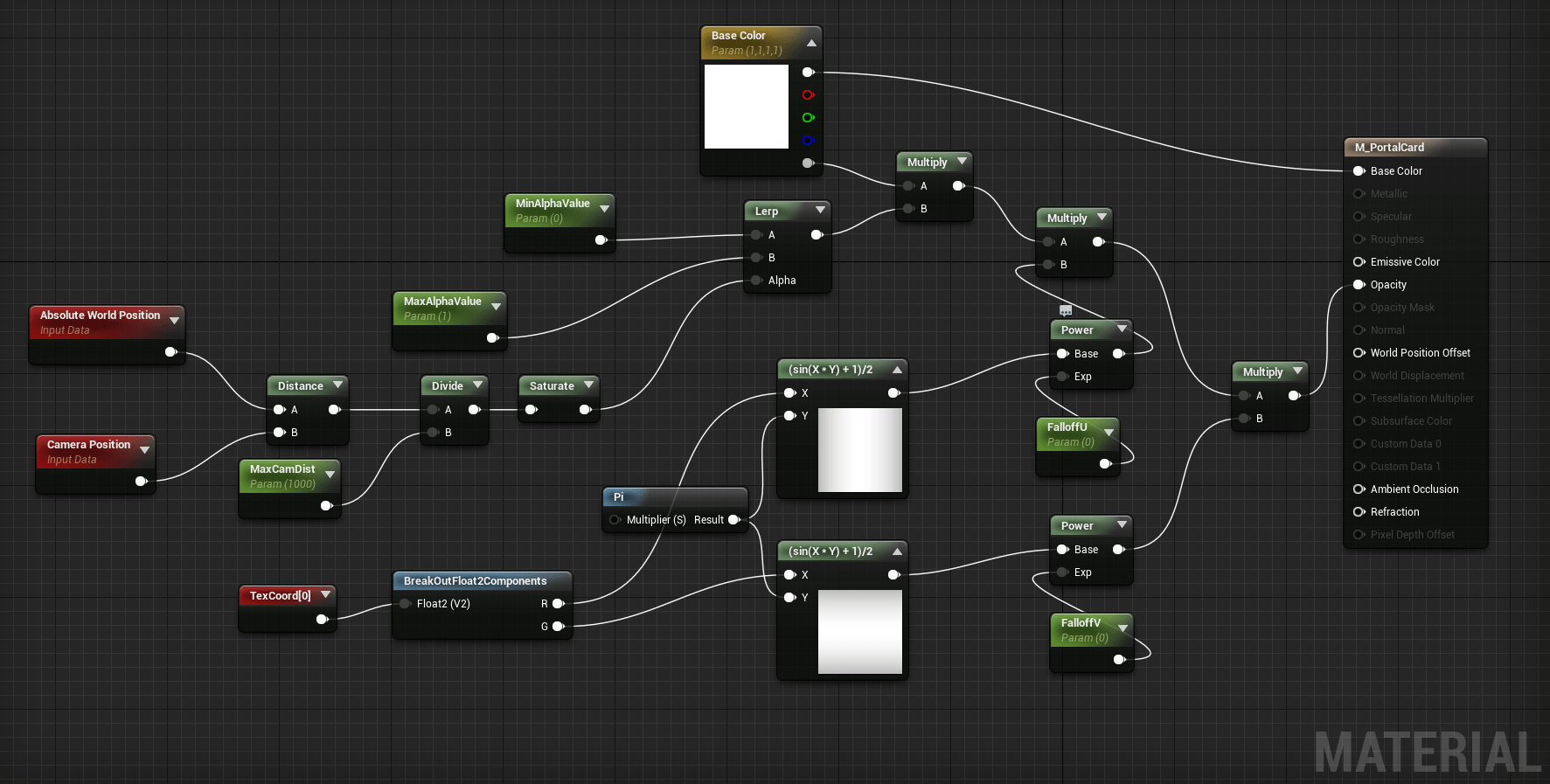
Job’s done, see you in the next one!
P.S.:
Video of the GDC talk:


