
I’m still staying on the subject of manipulating UV coordinates to produce shapes and effects, and this time, I’m throwing a known concept in the mix: displacement. This shader is also going to be pretty simple, but it’s going to be a stepping stone for some of the future effects. Hopefully, it will also help you get more comfortable with simple shaping functions. The effect this shader will produce is shown in the featured image. It’s just a simple displacement effect, which is also not moving. However, the “interesting” part lies in the fact that there are no guiding textures involved, and there’s plenty of control concerning the frequency of the displacement lines etc.
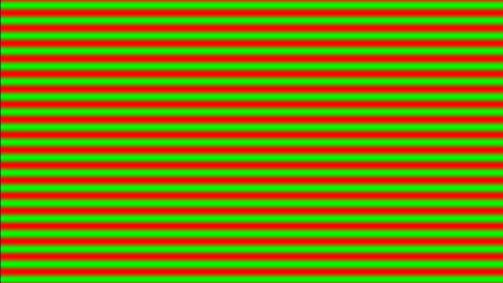
The way the image effect works is by generating a pattern inside the fragment shader which it then uses to displace the colors based on it. Specifically, the pattern looks like this:
 It’s basically a repeating gradient from pure red to pure green. Then, with a similar technique as the one discussed in the previous post on waving displacement, it uses the color information to apply the displacement. However, this shader does not distort the image on the y axis, only left and right.
Let’s see the code:
Shader "Custom/CustomWaveyDisplacement"
{
	Properties
	{
		_MainTex ("Texture", 2D) = "white" {}
		_Frequency ("Frequency", float) = 10
		_DisplAmount ("Displacement amount", float) = 1
	}
	SubShader
	{
		// No culling or depth
		Cull Off ZWrite Off ZTest Always

		Pass
		{
			CGPROGRAM
			#pragma vertex vert
			#pragma fragment frag

			#include "UnityCG.cginc"

			struct appdata
			{
				float4 vertex : POSITION;
				float2 uv : TEXCOORD0;
			};

			struct v2f
			{
				float2 uv : TEXCOORD0;
				float4 vertex : SV_POSITION;
			};

			v2f vert (appdata v)
			{
				v2f o;
				o.vertex = UnityObjectToClipPos(v.vertex);
				o.uv = v.uv;
				return o;
			}

			sampler2D _MainTex;
			float _Frequency;
			float _DisplAmount;

			fixed4 frag (v2f i) : SV_Target
			{
				fixed4 waveyDispl = lerp(fixed4(1,0,0,1), fixed4(0,1,0,1), (sin(i.uv.y * _Frequency) + 1) / 2);
				float2 displUV = float2(waveyDispl.x * _DisplAmount - waveyDispl.y * _DisplAmount, 0);
				fixed4 col = tex2D(_MainTex, i.uv + displUV);
				return col;
			}
			ENDCG
		}
	}
}
Only 2 properties are needed for the effect: one for the frequency of the generated lines and one for the amount of the desired distortion. After that, everything is pretty familiar up until the fragment shader.
The generation of the color information happens in line 48. All I do is use a lerping function that transitions from red to green. The “trick”, obviously, is in the third parameter. Let’s break it down a bit:
In order to get that smooth “wavey” look, I had to use the sine function, which is pretty smooth as we know. If I were to use something like a triangular wave, the generated texture would not look terribly different, however the result would be way more jagged and un-smooth. If that’s what you’d like, you can replace the third parameter of the lerp function with this:
abs(fract(i.uv.y * _Frequency) – 0.5) * 2.0
Moving back to why that sine call looks like this. As we know, the third parameter of a lerping function should have a value from 0 to 1. However, the sine function returns values from -1 to 1, which doesn’t quite work for us. That’s why I add 1 and divide the result by 2, to map the value in the (0, 1) spectrum. Finally, let’s move in the actual sine call and its parameter. UV coordinates go from 0 to 1, so getting the sine of just “i.uv.y” would not be too exciting as it would just be a simple gradient. However, by multiplying the y coordinate of the UVs by the frequency, it maps the result in the (0, _Frequency) spectrum, making the sine function go through its values multiple time, and thus creating the repeating gradient pattern.
After the color information is generated, it’s then used in line 49 to create the coordinates to add to the original UV coordinates of the screen. The formula is pretty simple: if the texture is red, I add the displacement amount, while if it’s green I subtract it. This is only applied on the x coordinate in order to distort the image solely on the x axis. After I get the displacement coordinates, I add them to the original UV coordinates and then return the standard color, as always.
While this was probably too simple, it was worth to explain it in a separate post, as this very effect will be part of the glitch image effect which I’ll share in a future post. So, stay tuned for that! Until then, see you in the next one!


