
Boy was it hard to name this post! And still, the name is not entirely accurate but I think it does a pretty good job of describing this “technique”. Basically, I’m following up on some of my previous tweets to share with you 2 simple shaders. That’s right, this time you have two brand new shaders! I’d bet some of you have already fainted with excitement but, thank goodness, I’m not a betting man. The reason I’m providing 2 shaders is because the effect is quite similar and it’s based on the same premise: 3 colors assigned to an object based on a directional light. And I believe this is also a great opportunity to mention the immense value of the dot product.
The humble dot
Let’s talk about everyone’s favorite subject: math! More specifically, the dot product between 2 vectors, and why it is such a huge deal. Basically, when you want to see the orientation of an object in relation to another object , the dot product is there for you.
The dot product of the vectors A and B, or A • B, will give you a scalar, meaning a number. This number will be equal to:
||A|| ||B|| cos(θ)
where θ is the angle between the two vectors.
Even when I knew that formula, at first, I still didn’t get about how it helps to see if an object faces another object, and how to use that number. So, here’s a simplified explanation of the dot product:
- If the 2 vectors are facing in the exact same direction, A • B = -||A|| ||B||
- If the 2 vectors are facing in the exact opposite direction, A • B = ||A|| ||B||
- If the 2 vectors are perpendicular, A • B = 0
Those are the more basic rules, and as one can extrapolate from those data, these are some additional rules:
- If the angle between the 2 vectors is in the (0, 90) spectrum (so, from almost facing the same way to almost being perpendicular), A • B ∈ (0, ||A|| ||B||)
- Similarly, if the angle is in the (90, 180) spectrum (almost perpendicular to almost in opposite directions), A • B ∈ (-||A|| ||B||, 0)
In most cases, you will use normalized vectors for your dot product, so ||A|| = ||B|| = 1, which, for the aforementioned rules, it means this:
- If the 2 vectors are facing in the exact same direction, A • B = -1
- If the 2 vectors are facing in the exact opposite direction, A • B = 1
- If the angle between the 2 vectors is in the (0, 90) spectrum, A • B ∈ (0.0, 1.0)
- Similarly, if the angle is in the (90, 180) spectrum, A • B ∈ (-1.0, 0.0)
How interesting! Now our values go from -1 to 1. And if we were to say (A • B + 1.0) / 2.0, we would have the dot product of the two vectors mapped in the (0.0, 1.0) spectrum. And, as mentioned in the previous post, if you can get a value in the (0, 1) spectrum, you can do a bunch of cool stuff with it! The (-1,1) spectrum also works pretty well as you’ll see in the shaders below.
Directional 3-color gradient coloring
The first effect that I will discuss is the one shown here:
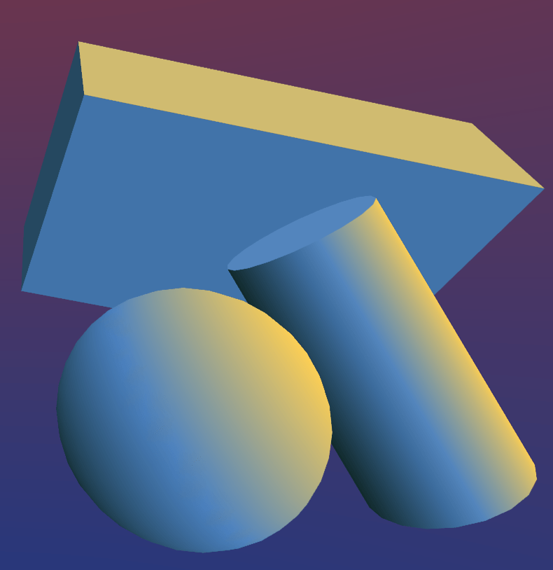 Basically, all the shader is doing is getting the direction of the directional light and, based on that, it lerps between 3 colors to give the final color of the object. If you want, you can just assign the colors as the one darker than the other so that you can basically “fake” lighting (yeah yeah, I know, everything in graphics is faked either way), or you can mess around with the color palette and get some very interesting results. Let’s jump straight to the code:
Shader "Unlit/DirectionalColoring"
{
	Properties
	{
		_LightColor("Light Color", Color) = (1,1,1,1)
		_MiddleColor("Middle Color", Color) = (1,1,1,1)
		_DarkColor("Dark Color", Color) = (1,1,1,1)
	}
	SubShader
	{
		Tags { "RenderType"="Opaque" }
		LOD 100

		Pass
		{
			CGPROGRAM
			#pragma vertex vert
			#pragma fragment frag
			// make fog work
			#pragma multi_compile_fog

			#include "UnityCG.cginc"

			struct appdata
			{
				float4 vertex : POSITION;
				float3 normal : NORMAL;
			};

			struct v2f
			{
				UNITY_FOG_COORDS(1)
				float4 vertex : SV_POSITION;
				float3 color : TEXCOORD0;
			};


			fixed4 _LightColor;
			fixed4 _MiddleColor;
			fixed4 _DarkColor;

			v2f vert (appdata v)
			{
				v2f o;
				o.vertex = UnityObjectToClipPos(v.vertex);
				half3 normal = normalize(mul(unity_ObjectToWorld, half4(v.normal, 0))).xyz;
				half lightDot = clamp(dot(normal, _WorldSpaceLightPos0), -1.0, 1.0);
				if (lightDot > 0) {
					o.color = lerp(_MiddleColor, _DarkColor, lightDot);
				} else if (lightDot < 0) {
					o.color = lerp(_MiddleColor, _LightColor, abs(lightDot));
				} else {
					o.color = _MiddleColor;
				}
				UNITY_TRANSFER_FOG(o,o.vertex);
				return o;
			}

			fixed4 frag (v2f i) : SV_Target
			{
				fixed4 col = fixed4(i.color, 1);
				UNITY_APPLY_FOG(i.fogCoord, col);
				return col;
			}
			ENDCG
		}
	}
}
As you can see, this shader was started with the unlit shader as a base. This one in particular doesn’t use any textures, so it only has the 3 colors as its properties. The “_LightColor” corresponds to the color on the side that faces the light (it’s also a keyword used by unity, but here’s its overriden so don’t worry about that). The “_MiddleColor” is for when the light is not facing directly or away from the specific area of the object. Finally, the “_DarkColor” is for the side that looks away from the light.
The whole color calculation process is actually done inside the vertex shader, not the fragment shader as one would expect. This is not necessary, but I chose to do that there so that I wouldn’t have to pass the normals in the fragment shader. In line 46 I calculate the normal vector and then, in line 47 I use it to calculate the dot product between it and the direction of the directional light in the scene, given by the “_WorldSpaceLightPos0” built-in value. This dot product is clamped between -1 and 1 and, thus:
- If the dot product is positive, the current vertex should have a color between the darkest and the middle color, since it is closer to looking away from the light.
- If the dot product is negative, the current vertex should have a color between the middle and the lightest color, as it is closer to facing the light.
- If the dot product is 0, the vertex normal is perpendicular to the light, so the color should be the middle one.
This is exactly what happens in lines 48-54. I lerp the colors using the dot product (remember to use the absolute value in the second case) and I store the color in a parameter which I then pass in the v2f struct for the fragment shader.
Then, in line 61 I just get that value and return it.
Directional 3-colored cel coloring

This shader follows the exact same logic as the previous. In this case, however, I wanted a clean banding between the colors, to give that cel shading effect. In order to make it more usable, I also had to add some parameters to adjust the percentage of the spectrum each color band covers. Will go more into specifics after we see some code:
Shader "Unlit/DirectionalCelColoring"
{
	Properties
	{
		_LightColor("Light Color", Color) = (1,1,1,1)
		_MiddleColor("Middle Color", Color) = (1,1,1,1)
		_DarkColor("Dark Color", Color) = (1,1,1,1)
		_Threshold1("Threshold 1", Range(0, 1)) = 0.33
		_Threshold2("Threshold 2", Range(0, 1)) = 0.66
	}
	SubShader
	{
		Tags { "RenderType"="Opaque" }
		LOD 100

		Pass
		{
			CGPROGRAM
			#pragma vertex vert
			#pragma fragment frag
			// make fog work
			#pragma multi_compile_fog

			#include "UnityCG.cginc"

			struct appdata
			{
				float4 vertex : POSITION;
				float3 normal : NORMAL;
			};

			struct v2f
			{
				UNITY_FOG_COORDS(1)
				float4 vertex : SV_POSITION;
				float lightDot : TEXCOORD0;
			};


			fixed4 _LightColor;
			fixed4 _MiddleColor;
			fixed4 _DarkColor;

			v2f vert (appdata v)
			{
				v2f o;
				o.vertex = UnityObjectToClipPos(v.vertex);
				half3 normal = normalize(mul(unity_ObjectToWorld, half4(v.normal, 0))).xyz;
				half lightDot = clamp(dot(normal, normalize(_WorldSpaceLightPos0)), -1.0, 1.0);
				o.lightDot = (lightDot + 1) / 2;
				UNITY_TRANSFER_FOG(o,o.vertex);
				return o;
			}

			float _Threshold1;
			float _Threshold2;

			fixed4 frag (v2f i) : SV_Target
			{
				fixed4 col;
				if (i.lightDot > 0 && i.lightDot < _Threshold1) col = _LightColor;
                else if (i.lightDot > _Threshold1 && i.lightDot < _Threshold2) col = _MiddleColor;
				else col = _DarkColor;
				UNITY_APPLY_FOG(i.fogCoord, col);
				return col;
			}
			ENDCG
		}
	}
}
The basic thinking is exactly the same, but the execution is a bit different. I added two more properties, “_Threshold1” and “_Threshold2” which determine the percentage of the dot product spectrum for each color band.
Up until line 49, everything is exactly as you’d expect from the previous example. In line 50 I mapped the dot product in the (0, 1) spectrum and then I assigned that value to a field named “lightDot” which I declared in the v2f struct in line 36. That was so that I could pass this value in the fragment shader this time.
BUT WAIT!
Why am I using the fragment shader this time to do the color calculations? In the other one it was done in the vertex shader somewhat arbitrarily, but here, it’s different. As we want a crisp color band on our objects we can’t calculate the colors on the vertex shader because it won’t be so accurate. In most cases, you will have more pixels on an object than you have vertices. Therefore, while it’s more expensive to do the calculations on the fragment shader, it’s also more precise in terms of color. In fact, if you did the calculations in the exact same manner but in the vertex shader, you’d end up with something like this:
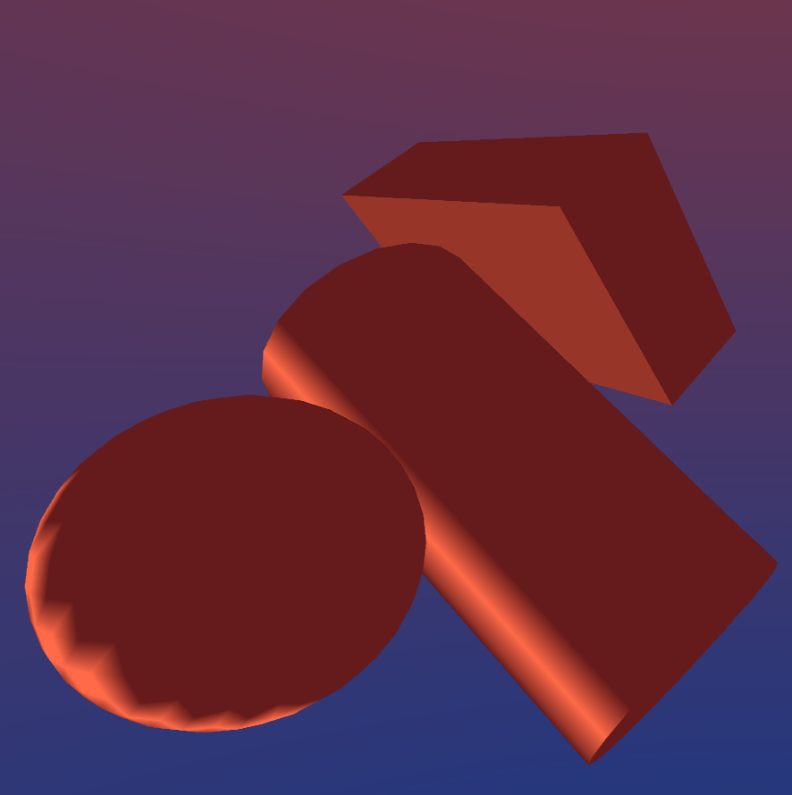 Now, you might want your game to be as ugly as sin, I don’t judge. But this result is an abomination, an utter eyesore, and I personally would not use it.
Besides, all that, in lines 61-63 of the fragment shader I do simple comparisons to determine the color of the object:
- If the lightDot is smaller than the first threshold, return the lightest color, since 0 in the lightDot means that the area is facing the light (remember, the dot is now mapped to (0,1), not (-1,1).
- If it’s larger than the first threshold and smaller than the second, return the middle color.
- If the lightDot is larger than the second threshold it means it’s closer to 1 and that the area is facing away from the light source.
Keep in mind that “if” conditions inside the fragment shader are not the most efficient way to achieve an effect. It would probably be better to use the “step” function or something similar to avoid the conditions. But for the sake of clarity and readability I keep the “if” blocks in the demonstrated shaders, in order to make the posts more beginner-friendly.
Finally, full disclosure, the second shader might demonstrate some weird behavior, probably due to the fact that some elements are calculated in the vertex shaders and others in the fragment shader. For now I’m keeping it like this as an example of an interesting shader variation.
Conclusion
Dang, this was a long post. But hopefully I gave you a pretty good idea as far as the value of the dot product is concerned. You probably have already encountered it multiple times and I can assure you that you’ll see more interesting uses of it in later posts. Until then, see you in the next one!


